Scatter Vector
Last Change: 2025-08-27 #dba #jta
Why using Scatter Vector
Traditional ADMS is intrinsically close to isotropic by design. But real-world engineering problems are not always isotropic.
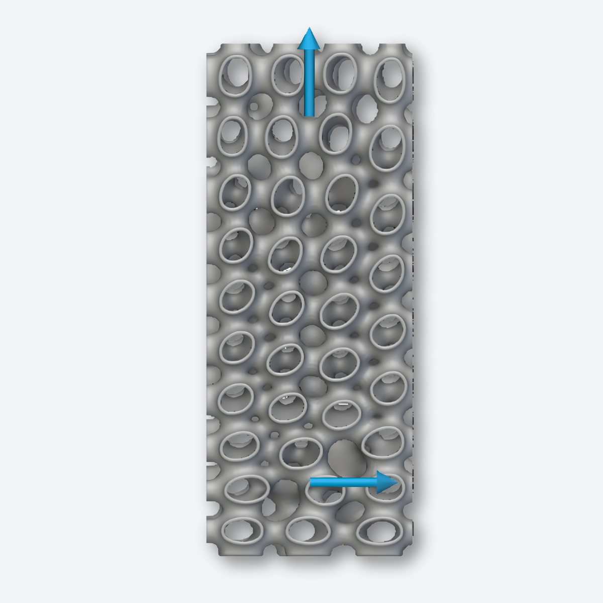
Scatter Vector gives users direct control over local geometric stretching through vector fields. Instead of uniform behavior in all directions, the geometry can now be intentionally biased.
You can introduce anisotropy as desired by using a scatter vector.
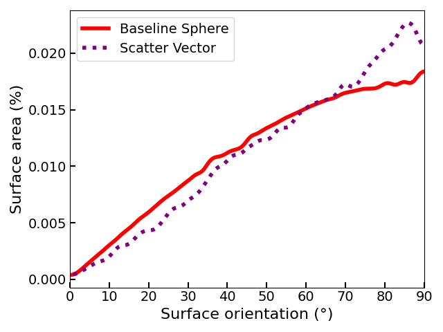
A Gauss map visualizes the distribution of surface normal directions across a geometry and is therefore commonly used to evaluate the isotropy or anisotropy of a structure.
The figure below compares the Gauss maps of a sphere and an ADMS structure with a scatter vector applied in the Z direction.
After applying the scatter vector, a pronounced peak deviation near 90° can be observed, clearly indicating the introduction of anisotropy.
How to use Scatter Vector
How it works
-
Users define one or multiple vectors at various points across the volume
-
Vector direction determines where the geometry stretches
-
Vector magnitude (unit: mm) defines how much local stretching occurs
-
Two vectors per point enable multi-directional deformation
Applying scatter vectors allows ADMS to transition from near-isotropic to purposefully anisotropic behavior.
This feature enables:
-
Directional stiffness or compliance
-
Load-path-aligned structures
-
Local reinforcement without redesigning the envelope
Scatter Vector expands ADMS from a passive adaptive geometry into an actively guided structural system.