Tutorial For Basic Features
Last Change: 2026-01-27 #JT
Quick-start example
The Spherene connector generates Adaptive Density Minimal Surfaces (ADMS) geometry based on a given envelope. In addition to the basic functionality of creating an ADMS with constant density, the connector offers four advanced capabilities as the basic features:
- Generate an ADMS with varying densities, allowing precise control over material distribution, and therefore, material properties.
- Generate an ADMS with varying surface bias to introduce controlled variation in surface morphology.
- Generate ADMS in sharp edges or thin regions—or prevent ADMS generation in specific areas—by using a density field envelope (
dfenv). - Generate cavities in the ADMS geometry, which is useful for integrating inlets, outlets, or other functional features.
In this section, we use a simple example with a cone-shaped envelope to demonstrate how to use the Spherene connector and its advanced functions. For more complex design tasks, refer to the advanced examples. You can download all the examples here.
Example with varying density
Density is defined as the percentage ratio of the generated Spherene volume to the envelope volume: , where the density reference thickness is an input parameter in the Spherene compute block.
Density reference thickness (DRT) defines the reference wall thickness of the generated Spherene geometry. This reference thickness is use to compute the density when generating the spherene geometry. Normally this would take the nozzle size of your 3D printer or the thickness you wish for computing density of spherene geometry. The default unit of DRT is millimeters, and it should be a float value greater than 0.1. Lower DRT values produce more complex geometries with higher genus (i.e., more holes or handles) but also significantly increase computational cost. Halving the DRT can increase computation time by up to 8× and memory usage by up to 6×.
The Density attribute in the Spherene Compute block controls the density distribution of the generated Spherene geometry. If a single point-value pair is provided, the density is treated as constant. If a point map with multiple point-value pairs is assigned, the resulting Spherene geometry will have varying densities.
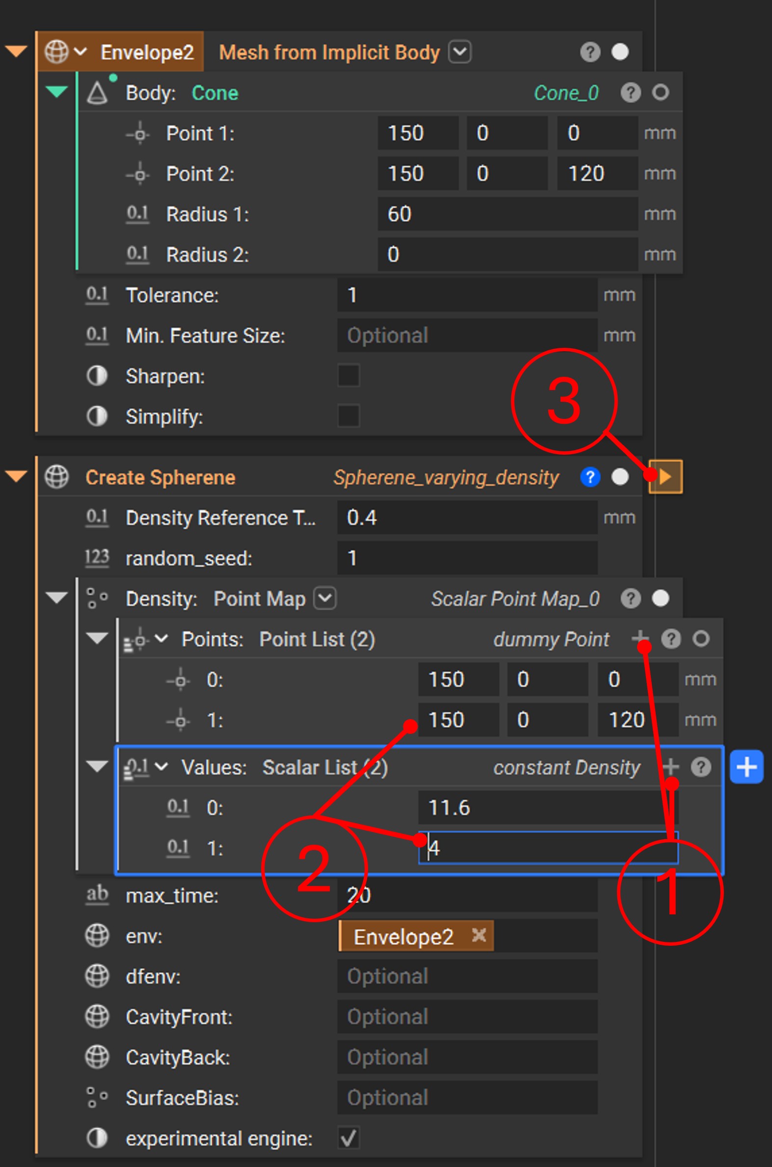
In this example, we define two points in the Density attribute, creating a density gradient between them. The workflow is as follows:
- Click the
+button (position 1) in the point map under theDensityattribute to add a new point–value pair. - Enter the coordinates and corresponding value for the new point–value pair (as shown in position 2).
- Click the
Runbutton (position 3) to start the computation.
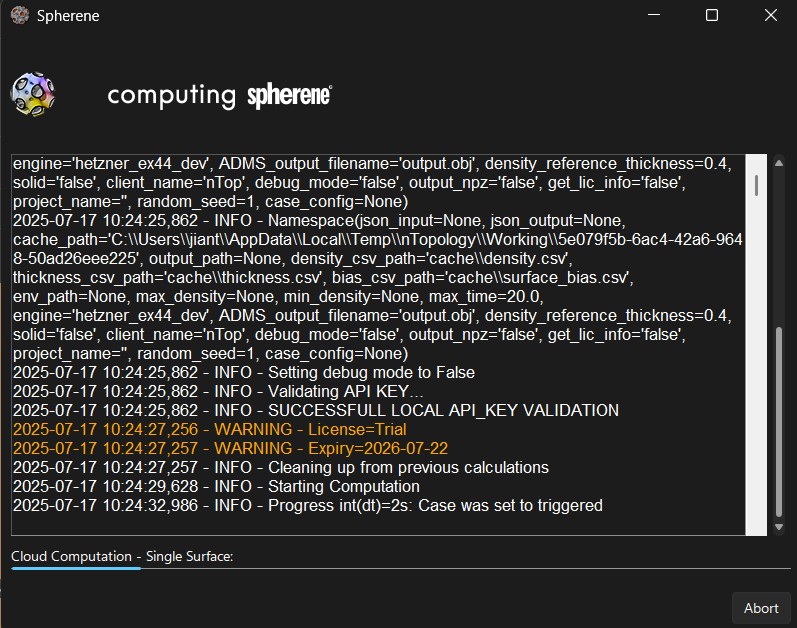
Once the computation starts, a computing window will appear. You can stop the process at any time by clicking Abort. When the computation is complete, the window will close automatically and deliver the computed spherene geometry.
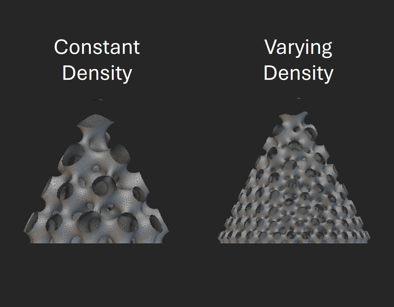
The following figure compares Spherene geometries with constant density and with a density gradient.
A more complex point map can be assigned to the Density attribute for advanced design tasks (see advanced examples). The Spherene connector also provides a helpful tool, Scalarfield to Point Map  , which generates a point map from a scalar field by sampling points and scaling the values to a specified range. For usage examples of
 Scalarfield to Point Map, refer to the advanced examples.
Example with varying Surface Bias
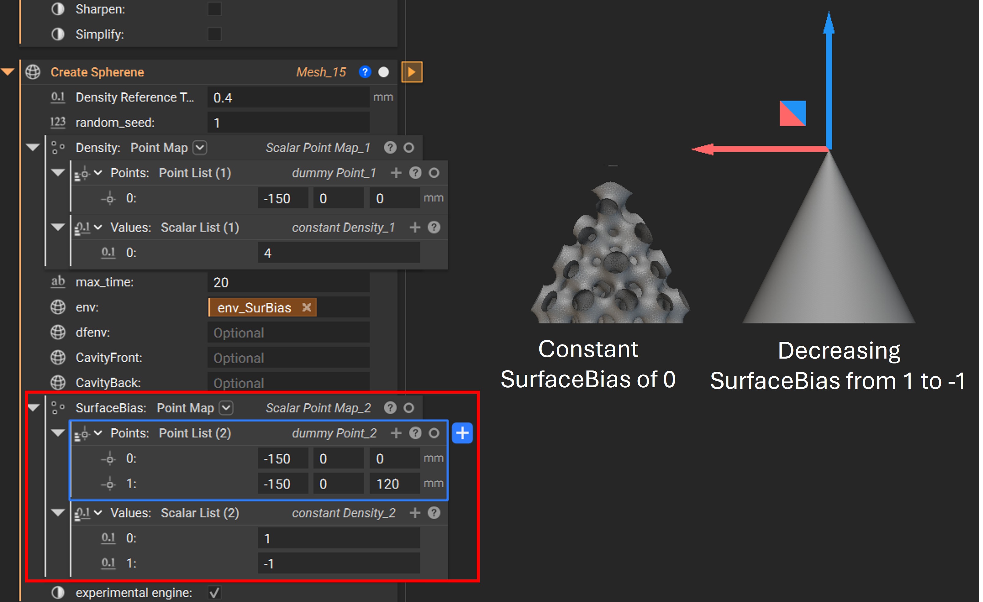
Similar to Density, you can control the surface bias of the generated Spherene geometry by assigning a point map to the SurfaceBias attribute. Surface bias determines how the minimal surface shifts from its ideal position toward the negative or positive direction along its normal.
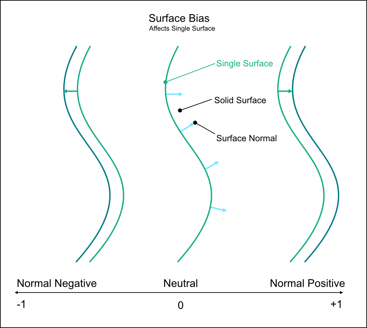
In the following example, the surface bias is varied from -1 at the bottom to 1 at the top tip of the cone.
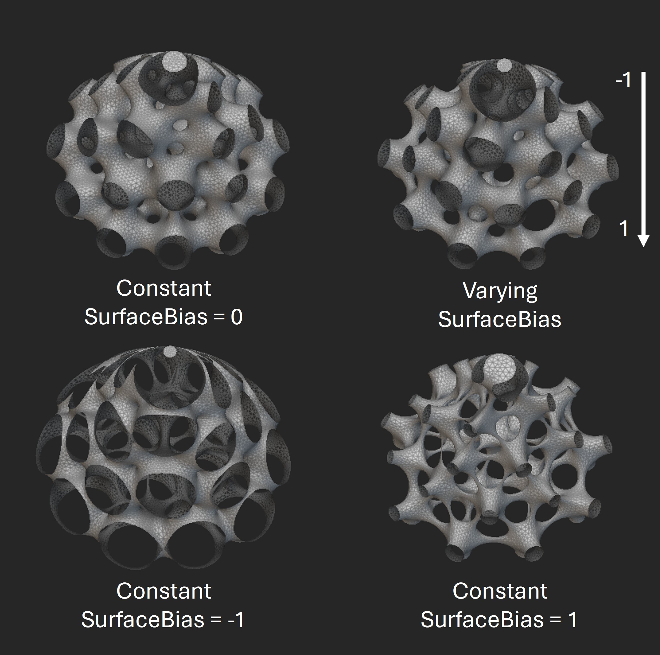
The figure below shows a comparison of Spherene geometries generated with different surface bias settings. Noticeable differences in surface morphology can be observed as the surface bias is adjusted.
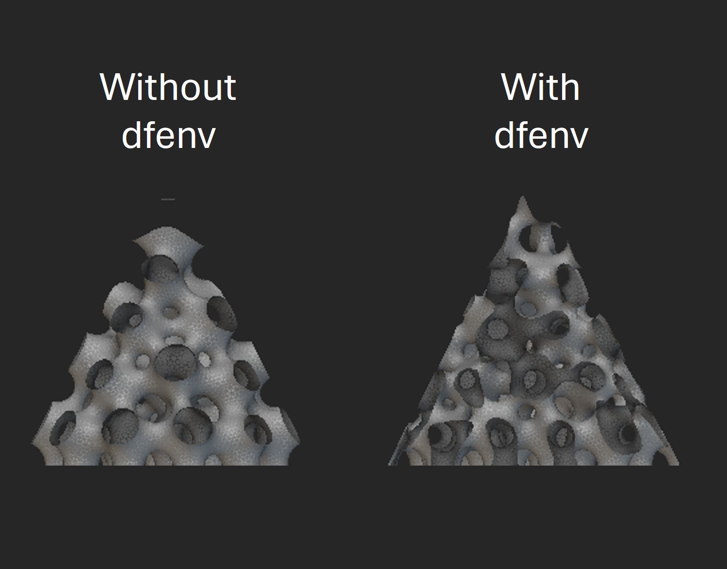
Example with density field envelope dfenv
The dfenv attribute allows you to input a mesh as the density field envelope. When a dfenv is defined, the Spherene geometry is first generated using dfenv as the envelope, then trimmed by the original envelope env to produce the final geometry. This allows Spherene structures to be generated at sharp edges or in thin regions where material might otherwise be insufficient, or to be excluded from specific areas where generation is not desired.
In the following example, we aim to generate Spherene structures at the sharp tip and edges of a cone. To achieve this, we define a box-shaped dfenv (shown in blue) that is larger than the original cone envelope env (shown in gray).
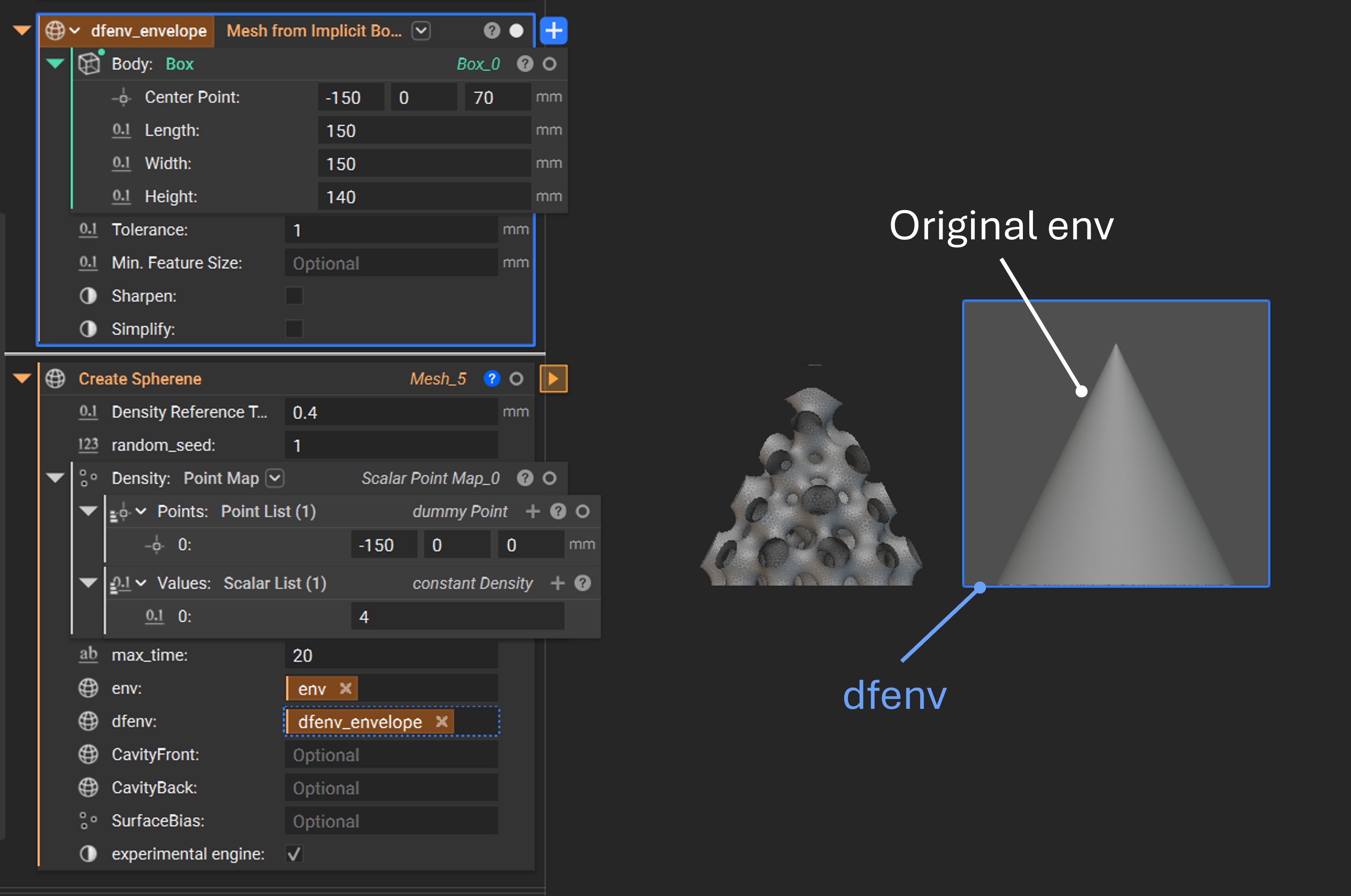
From the result below, you can see that the Spherene structure is successfully generated even at the sharp edges and the top tip with the dfenv.
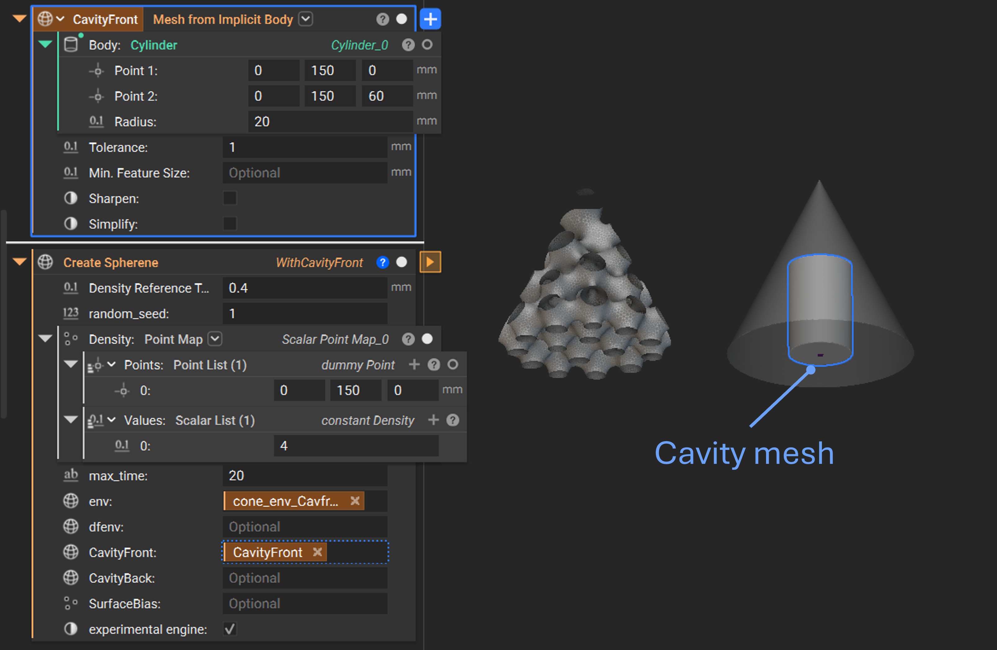
Example with cavity
You can introduce a cavity into the Spherene geometry by simply assigning a cavity mesh to one of the cavity attributes: CavityFront or CavityBack. This is especially useful for integrating inlets, outlets, or other functional features.
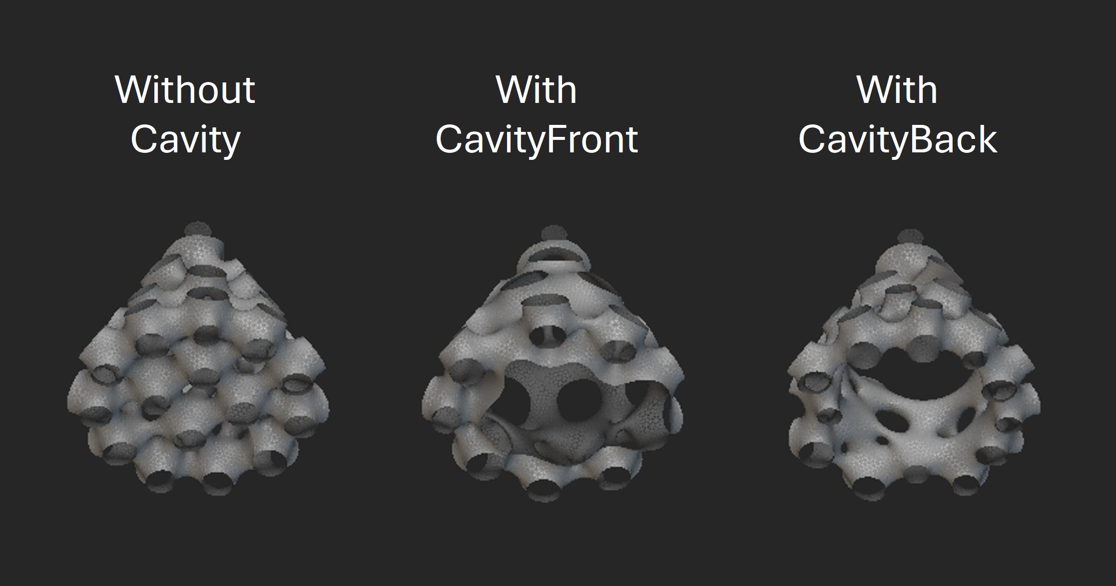
In the following example, a cylindrical cavity is introduced at the bottom of the cone envelope by assigning a cylinder mesh to either the CavityFront or CavityBack attribute.
By selecting either CavityFront or CavityBack, the cavity surface will be landed on different spaces of the ADMS structure. The following figure shows a comparison between a Spherene geometry without a cavity, with CavityFront, and with CavityBack.
Advanced Examples
The previous toy example is intended to demonstrate the basic usage of the Spherene connector. However, Spherene is capable of much more and can significantly enhance real-world design applications!
Below are several examples showcasing the integration of Spherene in advanced design scenarios. Detailed nTop settings and results can be explored in the accompanying example .ntop files from this link.
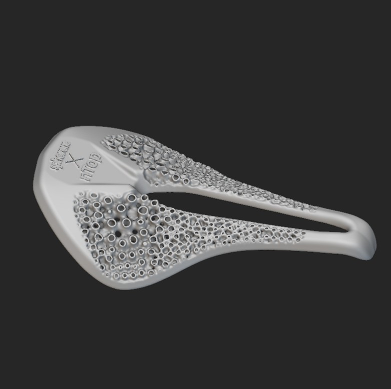
Lightweight bike seat using a Spherene lattice infill driven by mechanical modeling results
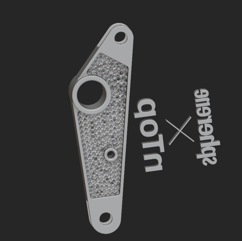
Topology optimization of a bracket with Spherene structure for various loading cases
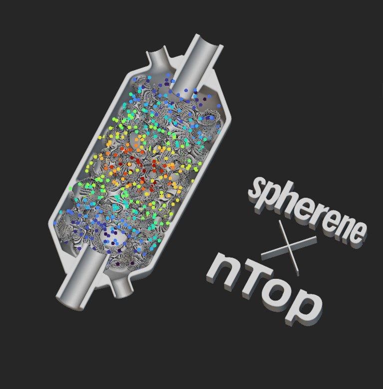
Heat exchanger with Spherene geometry
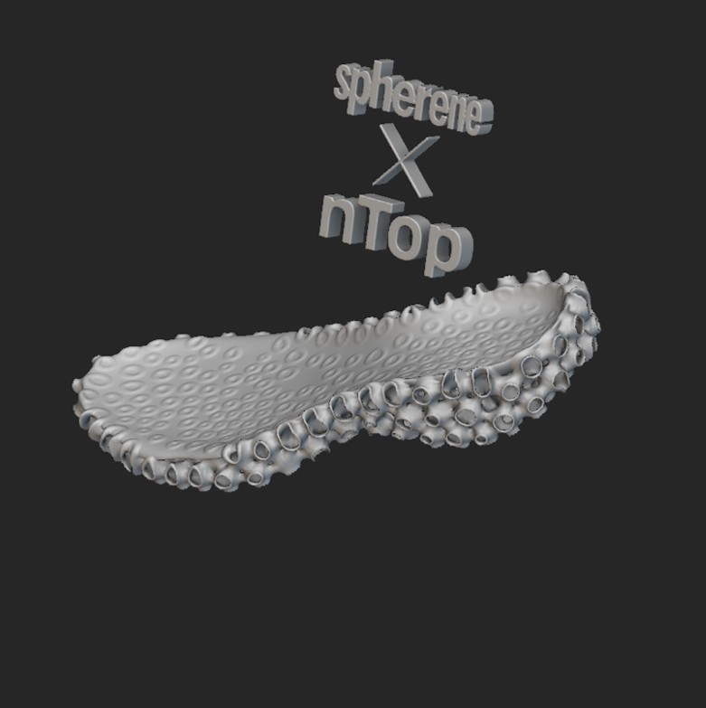
Lightweight shoe sole design with Spherene geometry